TinyGo on Pimoroni Cosmic Unicorn: Part 1

zegl
I recently bought a Pimoroni Cosmic Unicorn, it's a 32x32 pixel RGB LED display with a Raspberry Pi Pico W attached to it, plus some extras such as buttons, a speaker, and connections for driving it all via a a battery.
The Cosmic Unicorn comes with drivers and APIs for C/C++ and MicroPython for controlling the display, they both work great. My only annoyance is that the C/C++ driver is written in C++, and I got frustrated trying to keep my MicroPython app from OOM-crashing. So, I decided to try to build a driver for the Cosmic Unicorn in TinyGo.
TinyGo is a Go compiler and toolbox for embedded devices. TinyGo comes with "machine" packages for many devices, and includes hardware features like input/output over the GPIO pins and more. TinyGo doesn't support all features of the RP2040 which is the microcontroller on the Pico W, but hey, that's part of the challenge!
Looking at both the C++ implementation and the schematics of the device, I've been trying to debug how this thing works.
The LED matrix connects to 8 GPIO pins on the Pico. Called LED_SCLK (clock), LED_DATA, LED_LATCH, LED_BLANK, and LA_CTRL_0_3V / LA_CTRL_1_3V / LA_CTRL_1_3V / LA_CTRL_1_3V on the datasheet. I'm no electrical engineer, so I've had to search and debug my way to understanding what each pin does and what it works.
The official C/C++ SDK uses the "Programmable Input/Output" feature of the RP2040 which TinyGo doesn't support yet, so in this version we'll be controlling the LEDs over the CPU for the time being. The drawback is that a CPU powered version has to spend more time CPU time rendering, and has less time for computing what should be rendered, like some crazy animated effects.
It would be interesting to add PIO support to the TinyGo driver, but that's a story for another time (gotta save some ideas for a follow up blog post you know).
How do communicate with the matrix?
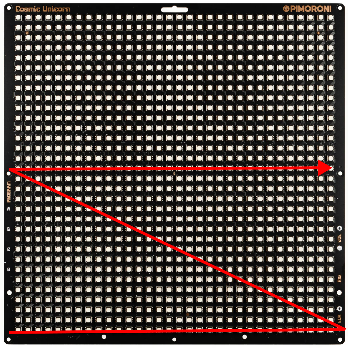
The matrix works by first using the LA_CTRL pins to specify which "row" to control and then using the other pins to write data to that row of pixels.
I first started by debugging how the row selector works. The board has 1024 pixels in 32 rows and 32 columns, but there is only 4 bits (0 to 15) for controlling which row to control. How does this work?
It turns out that the 32x32 "physical" layout is actually a 16x64 layout electronically.
Row "0" isn't 32 pixels wide, but rather 64 pixels wide, and is laid out like this:
How does the column pins work?
The column driver has 64x3 bits of memory. 3 bits for each LED for each pixel on the row. Each R, G, and B LED can only be "on" or "off".
To set the colors of the column, the COLUMN_CLOCK, COLUMN_DATA, COLUMN_LATCH and COLUMN_BLANK pins are used.
To set the data you have to "shift" it in into the memory one bit at a time. Every time clock changes from false to true (aka "rising edge"), the current value of the data pin is shifted in.
When "done" the memory will be laid out like this, with one bit per color per led, in R-G-B order.
RGBRGBRGBRGBRGB[...]RGB
0  1  2  3  4  [...]64
When "shifting" data in, we're starting from the "right" with the B byte of the 64th LED, then with the G byte, and so on.
We end the process by enabling the COLUMN_LATCH pin. The "memory" is now saved by the LED controller, and current will flow to the LEDs until we reset it, or move to another row.
And that's it in terms of controlling the LEDs, from now on, as long as we keep calling Draw() as fast as we can, our RGB data should keep rendering.
In the Go driver, the RGB data is stored in frames that will be alternating on the display.
const ROW_COUNT = 16
const FRAME_COUNT = 1 // TODO: Increase frame count to support more colors
const FRAME_COL_SIZE = 32 * 2 * 3

type CosmicUnicorn struct {
    frames     [FRAME_COUNT][16 * FRAME_COL_SIZE]bool
}
And to draw the data in frame, our Draw() function looks like this, which is implementing the row and column protocol as described above.
func (c *CosmicUnicorn) Draw() {
    for frame := uint8(0); frame < FRAME_COUNT; frame++ {
        for row := 0; row < ROW_COUNT; row++ {

            ROW_BIT_0.Set(row&0b1 == 0b1)
            ROW_BIT_1.Set(row&0b10 == 0b10)
            ROW_BIT_2.Set(row&0b100 == 0b100)
            ROW_BIT_3.Set(row&0b1000 == 0b1000)

            for idx := 0; idx < FRAME_COL_SIZE; idx++ {
                COLUMN_DATA.Set(false)
                b := c.frames[frame][row*FRAME_COL_SIZE+idx]
                if b {
                    COLUMN_DATA.Set(true)
                }

                COLUMN_CLOCK.Set(true)
                tick()
                COLUMN_CLOCK.Set(false)
            }

            tick()

            COLUMN_LATCH.Set(true) // latch high, blank high
            COLUMN_BLANK.Set(true)

            tick()

            COLUMN_BLANK.Set(false) // blank low (enable output)
            COLUMN_LATCH.Set(false)
            COLUMN_DATA.Set(false)

            // Brightness is correlated with how long the LEDs are
            // turned on before turning them off.
            // Based on testing. The maximum "on" time before
            // flickering seems to be around 1000µs when rendering
            // with 1 frames.
            time.Sleep(time.Microsecond * 1000 / 255 * time.Duration(c.brightness))

            COLUMN_BLANK.Set(true) // blank high (disable output)
            COLUMN_LATCH.Set(false)
            COLUMN_DATA.Set(false)
        }
    }
}
Testing
To test the display, I created a SetPixel() API that modifies c.frames:
func (c *CosmicUnicorn) SetColor(x, y int, col color.Color) {
    r, g, b, _ := col.RGBA()
    c.SetPixel(x, y, uint8(r), uint8(g), uint8(b))
}

func (c *CosmicUnicorn) SetPixel(x, y int, r, g, b uint8) {
    if x < 0 || y < 0 || x > 31 || y > 31 {
        return
    }

    x = (WIDTH - 1) - x
    y = (HEIGHT - 1) - y

    // map coordinates into display space
    if y < 16 {
        // move to top half of display (which is actually the right half of the framebuffer)
        x += 32
    } else {
        // remap y coordinate
        y -= 16
    }

    for frame := 0; frame < FRAME_COUNT; frame++ {
        c.frames[frame][y*FRAME_COL_SIZE+(x*3+0)] = b > 0
        c.frames[frame][y*FRAME_COL_SIZE+(x*3+1)] = g > 0
        c.frames[frame][y*FRAME_COL_SIZE+(x*3+2)] = r > 0
    }
...and created a 32x32 PNG image that I then parsed into RGB data:
//go:embed assets/*.png
var content embed.FS
type PixelSetter func(x, y int, c color.Color)
func drawImage(name string, ps PixelSetter) {
file, err := content.Open("assets/" + name)
if err != nil {
log.Println(err)
return
}
img, err := png.Decode(file)
if err != nil {
log.Println(err)
return
}
for y := img.Bounds().Min.Y; y < img.Bounds().Max.Y; y++ {
for x := img.Bounds().Min.X; x < img.Bounds().Max.X; x++ {
px := img.At(x, y)
ps(x, y, px)
}
}
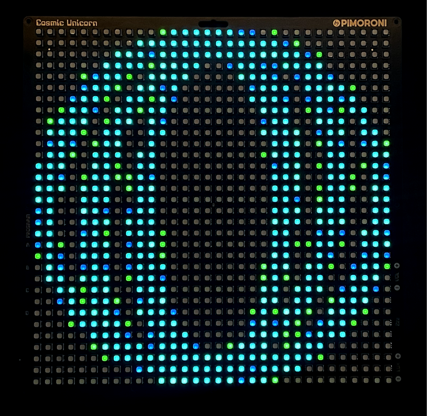
}And boom! Great success!
More colors
With this, I could render red, green, and blue pixels, or any combination of the three. For a total of 9 colors (3^2) including "off", so in practice it's only 8 colors.
I hadn't thought about this before, but the way to create colors that aren't 100% on, is to not power the LED all the time, but a portion of the time.
The official C/C++ driver does this by creating 14 frames that they are shifting the display between, and for each frame, each RGB LED can be either on or off, and by doing this fast enough the human eye doesn't notice the flicker, and "merges" the colors in the brain.
These 14 frames are what the documentation of the device refers to as 14-bit precision for colors, and means that you can have 14^3 = 2744 different colors.
The current 1-bit color implementation uses a simple logic, if the amount of a color is over 0, turn the led on.
for frame := 0; frame < FRAME_COUNT; frame++ {
    c.frames[frame][y*FRAME_COL_SIZE+(x*3+0)] = b > 0
    c.frames[frame][y*FRAME_COL_SIZE+(x*3+1)] = g > 0
    c.frames[frame][y*FRAME_COL_SIZE+(x*3+2)] = r > 0
}
RGB #010101 renders the same as #FFFFFF, and this is obviously not great as any normal picture would just be white.
To test with multiple colors, I increased FRAME_COUNT from 1 to 2, and added a on function to calculate if this color should be on for this frame. If the value is between 0 and 84, the LED is off, if it's between 85 and 169 it's on on the first frame, and if it's 170 or higher it's on on both frames.
on := func(val uint8, frame int) bool {
if val < 255/3 {
return false
} else if val < 255/3*2 {
return frame == 1
} else {
return true
}
}
for frame := 0; frame < FRAME_COUNT; frame++ {
c.frames[frame][y*FRAME_COL_SIZE+(x*3+0)] = on(b, frame)
c.frames[frame][y*FRAME_COL_SIZE+(x*3+1)] = on(g, frame)
c.frames[frame][y*FRAME_COL_SIZE+(x*3+2)] = on(r, frame)
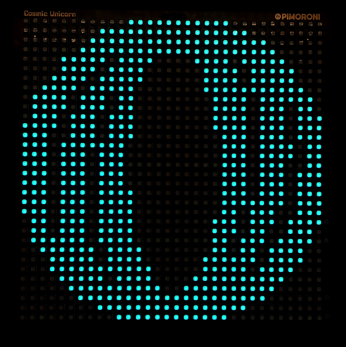
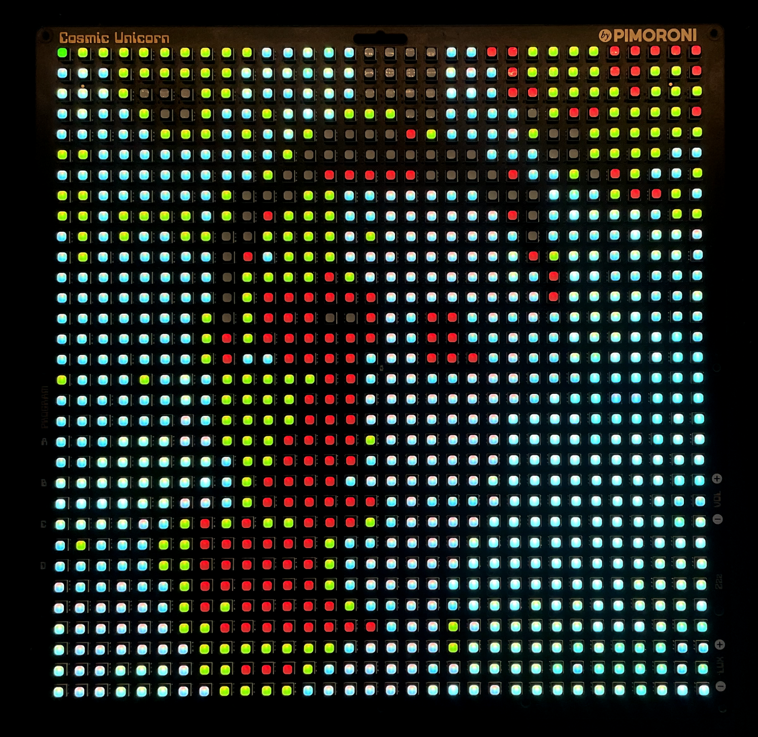
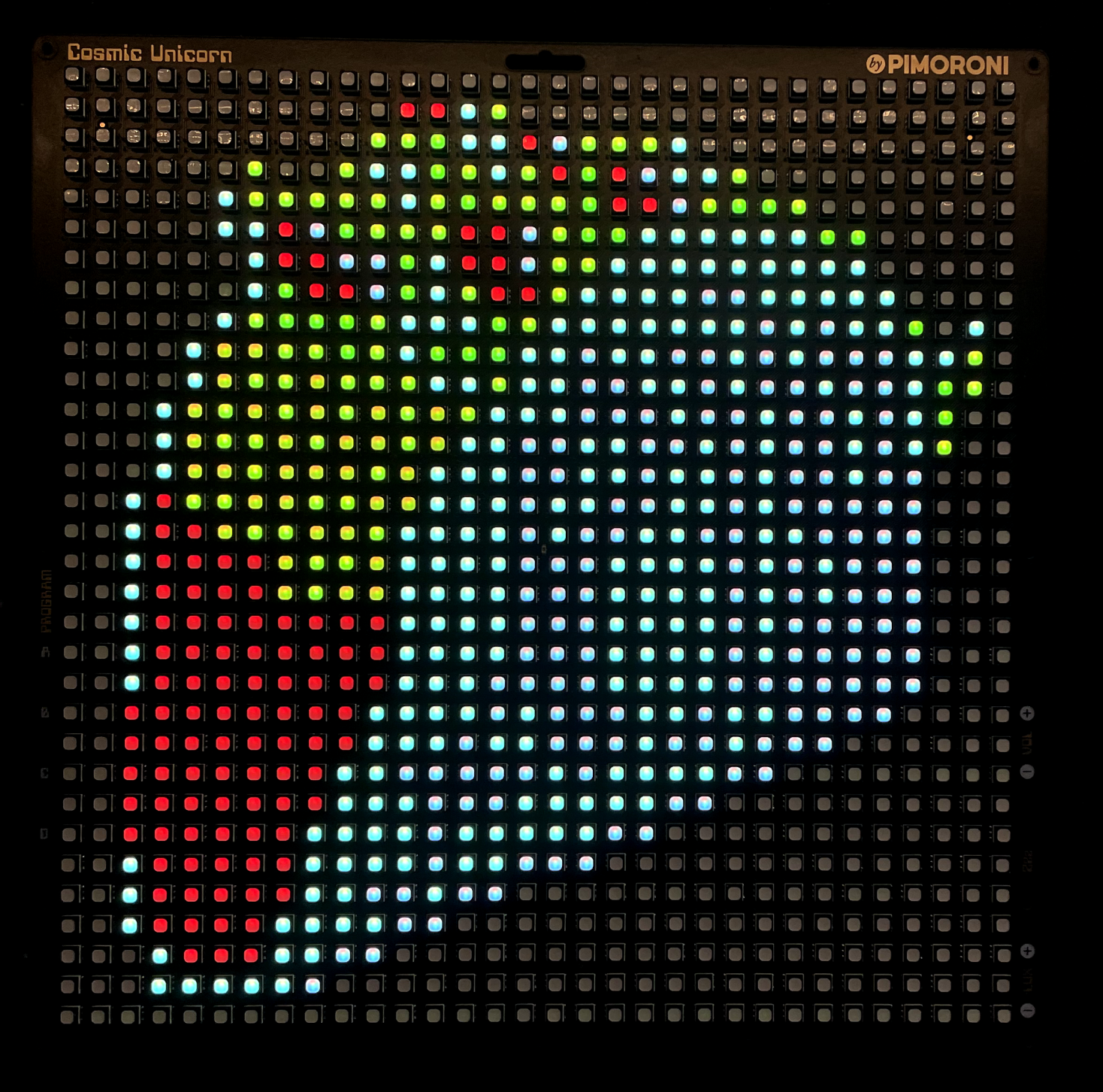
}Boom again! We can now render 27 colors.
The color representations are not great, and I want to squeeze in even more colors, but that will have to be a story for another time.
Here are some more examples, can you see what it is?
The driver and example code is up on github.com/zegl/go-cosmic-unicorn.
In future posts I'll be covering the process of increasing the amount of supported colors (with gamma correction?), PIO, and controlling the whole thing over WiFi. Neither PIO nor Wifi is supported by TinyGo yet, so that's going to be a fun journey!
So please subscribe to me here on Polar, and you won't miss it!
Peace out!
– Gustav